
In this script, we will discuss the most important topic of Operational Amplifier, we have already discussed this topic in another script
- What is Ideal Operational Amplifier?
- Characteristics of Ideal Operational Amplifier
- Two important properties of the ideal op-amp
- Math
- What is Virtual Ground
- What is Inverting Amplifier and Math
Now we will discuss
- Basic Op-Amp
- Op-amp Salient features or op-amp ideal characteristics
- Single-Ended Input
- Double-Ended Input (Differential Input)
- Double-Ended Output
- Common-Mode Operation
- What is a CMRR?
If you have any electrical, or electronics science doubts, then Contact Us.
.png)
Op-amp Salient features or op-amp ideal characteristics:
- Infinite voltage gain (Infinite open-loop voltage gain)
- Infinite input impedance
- Zero output impedance
- When the input voltage is zero then the Zero output voltage
- Infinite frequency bandwidth
- The infinite common-mode rejection ratio
- Infinite slew rate
Op-Amp different combinations:
1. Single-Ended Input
Single-ended input operation results when the input single is connected to one input with the other input connected to the ground. Figure 1.2 shows the signals connected for this operation.
.PNG)
Figure 1.1: a & b
We can see from this figure 1.2:a, that the input is applied to the plus(+) input, which results in an output having the same polarity as the applied input signal.
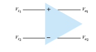
2. Double-Ended Input (Differential Input)
There is another possible way to apply signals at each input. This type of configuration is called a doubled-ended operation.

.png)
Double-Ended Output


Common-Mode Operation

What is a CMRR?
The CMRR in an op-amp is a common mode rejection ratio. The op-amp has two input terminals which are positive and negative terminals and the two inputs are applied at the same point. This will give the opposite polarity signals at the output. The overall operation is to amplify the deference signal while rejecting the common signal at the two inputs. Since noise is generally Common to both inputs, the differential connection tends to provide attenuation of this unwanted input while providing an amplified output of the difference signal applied to the inputs. This operating system is called common-mode rejection.
CMRR = Differential mode gain / Common-mode gain
Common Mode Rejection Ration of Op Amp
The CMRR is a differential connection in that the signals that are opposite at the inputs are highly amplified, whereas those that are common to the two inputs are only slightly amplified. The CMMR ratio can be applied to the operational amplifier. By using the condition of common mode rejection ratio, i.e. when both the input of the amplifier has the same voltages, then the output of the amplifier should be zero or the amplifier should be rejecting the signal.

.png&description=Op-Amp Basics || Op-amp ideal characteristics or Op-amp Salient features || Op-Amp different combinations)
0 Comments